Madcow Torrent Build – Part 6

I’ve been a little distracted and have not been posting as regularly as planned. I’ve more or less finished the main build. Since the last post, the rocket has been filled, primed, sanded, and painted. It’s hard to tell from the image below, but the darker color is a navy blue.

After putting some paint on the rocket, I epoxied the motor retainer on with some JB Weld. I went with an Aeropack retainer. Overall, the fit and finish of the retainer was great. I’m a little frustrated with the price of it though.

Now that the bulk of the build is done, I switched my attention to the altimeter bay. I decided to run redundant altimeters for the dual deploy. I ordered an Eggtimer Quantum for the primary, and a Perfectflite StratoLoggerCF for the redundant flight computer. The Eggtimer came as a kit, which was easy enough to solder up without a problem. The instructions were very detailed.

I took a look at the Madcow supplied altimeter sled and figured I could do much better on my own by 3d printing a custom altimeter sled. A few hours of 3d modeling got me to my first prototype. The overall goal of my design was to make this as customized as possible, but also make everything accessible. I’ve already spent more on this rocket than I’d like, so I want to be able to easily swap components out for use in other rockets. I’ll probably need another iteration to get all the sizes ironed out and places for wire tie downs, but it’s pretty close.

I went with a pair of 2S LiPo cells, 450 mAh, that are isolated from the flight computers by a pair of fairly hefty microswitches. The switches are turned off by inserting a 1/4″ rod through a tubing section printed in the sled itself. When fully assembled, the rod will go through the altimeter vent hole in the side of the rocket.

The first print off the printer turned out pretty close. I have some holes I need to resize, I need to add some holes to tie down some wires, but it is probably one iteration away from being ready. Once I’m happy with the print in PLA, I’ll probably switch to ABS or maybe even try NylonX.

Posted in Uncategorized | Comments Off on Madcow Torrent Build – Part 6

Madcow Torrent Build – Part 5

Things are starting to really take shape with the Torrent. I’ve finished a few steps where I didn’t take photos and post. I performed the following steps: glued the spacer ring to the altimeter bay/coupling, drilled the vent hole for the barometric pressure sensor, and glued together the plywood end piece for the altimeter bay. All of these steps followed pretty much exactly as on the Apogee Rockets website instructions.

The next step though is to prepare for the shear bolts. For dual deployment, the drogue will come out of the main booster tube, and the main chute will come out of the short section of tube between the nosecone and the altimeter bay. After the drogue deploys, it’s important that the upper portion of the rocket stay together to prevent the main cute from either deploying too high, or partially opening where the main chute doesn’t deploy at all. The kit does not come with shear bolts, or any instructions to add them. The Apogee tutorial on this build also does not have shear bolts, so I’m assuming that the intent of the kit is to rely on the friction fit of the nose cone to the extension tube to hold everything together, or possibly to use tape. Either way, I don’t really care for it. I added 2-56 nylon shear bolts to my kit. Each shear bolt should break at about 25 lbs of force. This is enough to easily hold everything together, but not too much that a deployment can break the pins and eject the main chute. Having never done dual deployment, I’m relying on advice from friends and some calculations. This is a rocket that I want to get a lot of miles out of. I’m afraid that the shear bolts will chew up the cardboard after several launches. Therefore, I removed two layers of cardboard from the inside of the tube and replaced it with 0.016″ brass sheeting.

The first step was to cut a 1″x1″ square of 0.016″ thick brass stock. I picked up a decent sized piece of the brass from the local hobby shop for a couple dollars. The piece was bent into the approximate curvature of the body tube. I then carefully scored the inside of the body tube and peeled up two layers of cardboard. This was approximately the thickness of the brass piece. 30 min epoxy was applied to the exposed cardboard and the brass piece was placed in the opening. I covered this with wax paper and used the coupling piece as a mold to press the brass piece into the cardboard while the epoxy cured.

After the epoxy was cured, I added another layer of epoxy over the brass piece and repeated the process. This resulted in a smooth surface so the nose cone will not catch. This was repeated three times for three shear bolts. The next step was to drill the pilot holes for the 2-56 screws. I did this with the nose cone attached so that the holes line up.

After the holes were drilled, I dripped in some thin CA to harden the cardboard area as well. Unfortunately, I didn’t have a 2-56 tap, so I placed another order on Amazon and will tap the holes at a later time.

I’m hoping to get the rocket in primer and paint soon. Still deciding on a color scheme, but thinking some combination of yellow and blue. While painting, I’ll start working on the altimeter bay. While not necessary for the level 1 certification, I’d like to at least get started on it.

Posted in Uncategorized | Comments Off on Madcow Torrent Build – Part 5

Madcow Torrent Build – Part 4

It’s time for this to take some shape and put the fins on. After dry fitting the fins, I applied epoxy to the root edge and attached them to the motor mount tube. The slots are a really tight fit and I did end up opening them up a bit with some 120 grit sandpaper.

After the epoxy cured, I added interior fillets.

The picture above shows the interior fillets to the motor mount. I also added some pure epoxy fillets at the fin/body tube joint as well, but didn’t take a photo. After the interior fillets dried, I added exterior fillets using 30 min epoxy loaded with glass microspheres. It was my first time working with this, and I wasn’t terribly happy with my skill level. I ended up using some glazing putty to clean and level them out. It doesn’t look all that pretty now, but it will be once all sanded and primed. I also started to fill some of the spiral seams.

I forgot to mention that I did also epoxy on the rear centering ring. I’m going to use an Aeropack motor retainer, so I applied painters tape to protect the area on the motor tube where the retainer will be to make sure I didn’t get any epoxy on it. I’ll put the retainer on after I paint the model. After cleaning the fillets and finish filling the spirals, it will be primer, paint, and dealing with the altimeter bay. I ordered an EggTimer Quantum which should be here in a few days. I still need to decide what to use as the backup. I also plan on 3d printing an altimeter sled to fit the components. At the rate winter is setting in, it may be spring before I get level 1 cert…

Posted in Uncategorized | Comments Off on Madcow Torrent Build – Part 4

Madcow Torrent Build – Part 3

I got carried away and progressed further with the build and forgot to take photos… The motor mount was installed the other day. I used 30 min epoxy to glue the forward centering ring to the main body tube. I did NOT glue the rear centering ring. I did dry fit it though to keep the motor mount centered. Note that this deviates from the Apogee installation method where they install the full motor mount at once.

After letting the motor mount fully cure, it was time to move on to the rail buttons. Based on the Apogee video instructions, the rear rail button is screwed through the body tube and into the rear centering ring. I am less than impressed by this. As shown in the photo below, the #6 wood screw is almost the same width as the centering ring. Assuming the hole is drilled in the precise center, the threads will cut almost to the edges of the centering ring. If there is any misalignment in drilling the pilot hole, the screw will blow out the edge of the plywood centering ring. Also, if I replace the rail buttons due to wear, repeated removing and replacing this screw will cause the hole to open up. I also fear stripping this hole out if the rail button puts any force on the screw. As an avid woodworking, screwing into the edge of plywood never really makes sense.

The forward rail button mount also left me less than impressed. The kit came with a small metal T-bolt like mount. The screw was a #6 stainless screw with about 1 mm thread clearance through the rail button. The fact that this was small and looked like it would put a lot of stress on the cardboard body tube made me think about upgrading it. I decided to instead use stainless T-bolts with a plywood backing plate. I ordered some Delron rail buttons with #8 stainless screws as well as some #8 stainless barbed T-bolts.


To mount the T-bolt, I cut a 1″ x 1″ scrap of 1/4″ thick plywood. I drilled a hole through the center of the plywood to allow the T-bolt to be inserted into the plywood. The plywood was sanded to have roughly a 4″ radius across it so it had full surface area to bond to the inside of the body tube. The 1/4″ plywood is actually about 3/16″ thick. This allows the T-bolt threaded portion to protrude about 1/16″ of an inch through the plywood.

After the rail button mounts were assembled, the body tube was marked to determine where to drill the holes. For the rear rail button, the block was placed as far back as possible without interfering with the rear centering ring. The front rail button was located just above the front centering ring. One thing to keep in mind is not to have the rail button mount interfere with the eyebolt on the front centering ring. I placed my rail buttons on the opposite side of the body tube as the eyebolt. After determining the location, I drilled holes through the body tube, wicked some thin CA into the exposed edges of the cardboard, and epoxied the rail button mounts in place with 30 min epoxy.

Since I used plywood just slightly thinner than the T-bolt, the shaft of the T-bolt actually went most of the way into the body tube. This helped with aligning the T-bolt as well as preventing the cardboard from collapsing if the railbuttons are over-torqued.

The next step will be installing the fins. In general, I feel that this kit has some very nice quality components coupled with some ridiculously bad decisions. To include a better rail button, backing plate, and T-bolt would have been a near negligible cost increase while providing much better quality. Granted, this is my first 4″ level 1 and 2 capable rocket, but there really is no reason to skimp on quality for something as minor as this.

Posted in Uncategorized | Comments Off on Madcow Torrent Build – Part 3

Level 1 Rocket Build – Madcow Torrent, Part 2

I’m pretty slow at building, and I tend to over do everything. Therefore, I decided to taper and fiberglass the fins. While it only adds about 5 grams of weight, it seals the fins, and the paint tends to coat them so much better. Besides, it adds a nice hard shell to fins to prevent minor nicks. The downside is that it takes time…

To start with, I rounded the leading edge and put a taper on the trailing edge. These are pretty thick plywood fins, so it took a while.

After sanding and cleaning the fins, I started laying up the fiberglass. I’m using 3/4 oz/yard woven fiberglass with West System epoxy. This is a hold-over from my RC airplane days. If done correctly, the fiberglass and epoxy adds only a small amount of weight. The trick is to drizzle only enough epoxy over the fiberglass to wet the weave, then squeegee any excess epoxy away. This will leave a slightly textured surface that will be removed by a subsequent coat. To squeegee the material away, I just use one of Jason’s old common Magic The Gathering cards (don’t tell him…).

I only applied fiberglass to the exposed surfaces. This process is pretty controversial as many people believe this adds weight with no real value as the fins are strong enough as they are. While true, I like the finish that I get and the paintability of the surface when done is amazing. I even do this to low power rockets. I compared the weight of fiberglass to sealing the fins with paper/CA, and the fiberglass came out slightly lower weight with a much better finish.

After curing, I’ll apply a second coat of epoxy (very thin, scraping most of the material off with a card), then a thin layer of glazing putty. I wet sand between all layers, careful not to sand too far into the weave.

Posted in Rocketry | Comments Off on Level 1 Rocket Build – Madcow Torrent, Part 2

Return to Rocketry – Madcow Torrent Build

We took a small break in robotics this year. After a several year hiatus, I decided to return to rocketry. My son convinced me that we should go big and each get our NAR level 1 high power certification. We discovered that he’s eligible to get his “Junior Level 1,” and thought we’d have good fun doing this together.

I decided the on the Madcow Torrent, while Jason is going for the LOC Fantom 438 EXL. In both cases, we wanted a very large level 1 that could be easily set up for dual deployment. This puts the base rocket kit in the $120-$140 range.

I received the package from Apogee Rocketry and was very excited. Well, I think Jason was more excited. This was advertised as a quality kit for getting into 4″ dual deployment.

The Torrent has arrived!

Opening up the bag, the kit included all of the structural components, two shock cords, a drogue and main parachute, and the altimeter bay with sled. Also included were two Nomex sheets. What was absent was any form of instructions. Luckily, it looks like this kit should build up like any other through the wall fin rocket construction.

Being very impatient, I went ahead and started assembling the motor mount. The first step was to epoxy the forward centering ring on the motor mount. I first roughed up the 38 mm tube to improve the epoxy adhesion, then used 30 min epoxy to attach the forward centering ring.

I wasn’t thrilled with the eye hook provided. After ordering some 1/4″-20 stainless steel forged eyebolts from Amazon, I received 6 mm threads instead. Returning the item and requesting a replacement, I again, received 6 mm threads. If I put my stubbornness aside, I could have simply used 6 mm bolts. However, opting to be difficult, I reverted back to the supplied hardware. The back-and-forth with Amazon set me back 4 days…

Posted in Rocketry | Comments Off on Return to Rocketry – Madcow Torrent Build

Sending Bluetooth Messages from Raspberry Pi to LEGO EV3 (stock firmware)

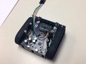
I recently came across a need to send messages from a Raspberry Pi to an EV3 running the stock EV3 firmware and programmed in EV3-G.   This pretty much limits the methods available to using the EV3-G Bluetooth Messaging block.  The official documentation for this block is far from great.  Luckily, there were some really good online resources for how to write the programs on the EV3 side as well as the Raspberry Pi side.  Notably, I found the following resources extremely helpful:

https://www.hackster.io/KKE/raspberry-pi-lego-mindstorms-ev3-bluetooth-communication-aa42e2

http://www.geekdroppings.com/2018/01/21/raspberry-pi-and-the-lego-ev3-connected-by-bluetooth/

However, what these resources did not include was how to pair the EV3 with the Raspberry Pi.  This took some digging and a lot of trial and error to accomplish.  I found that the sequence shown below does indeed work.  It should be noted that I’m performing this on a Raspberry Pi 3 B+ running the most up-to-date version of Raspbian as of the date that I’m authoring this post.

First and foremost, it is recommended to update the operating system and packages.  Using a terminal window, type:

sudo apt-get upgrade
sudo apt-get update

Next, we need to install Bluez.  Bluez is the official Linux stack for Bluetooth.  You can find more information regarding the Bluez package at:

https://docs.ubuntu.com/core/en/stacks/bluetooth/bluez/docs/

Specifically, we need the RFCOMM implementation to allow us to treat the Bluetooth module as a serial interface.  We also need the Bluetooth manager.  To install the Bluez and the Bluetooth Manager packages, type:

sudo apt-get install bluetooth bluez blueman

After installing this, you need to reboot the Raspberry Pi.  After the Pi reboots, you should now have two Bluetooth icons in the upper right corner of your desktop.


The next step is optional, but highly recommended.  The default Bluetooth name for a Raspberry Pi is ‘raspberrypi,’ which is not very exciting.  In particular, we intend to use our system at a robotics competition where there will likely be many Raspberry Pi’s.  To avoid conflicts, and just to be more descriptive, let’s assign a new Bluetooth broadcast name.  Create a new file named /etc/machine-info.  To create this file, you can type:

sudo nano /etc/machine-info

or use whatever text editor you prefer if you don’t like nano.  This should be a blank file unless you have already created this for another reason.  Add the line:

PRETTY_HOSTNAME=deviceName

where deviceName is the broadcast name you would like to use for your Raspberry Pi. I used pecanPie for my name, but you can use whatever you’d like.
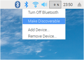
To start the pairing process, left click on the old Bluetooth icon, and it should open a drop down menu.  Select “Make Discoverable.”

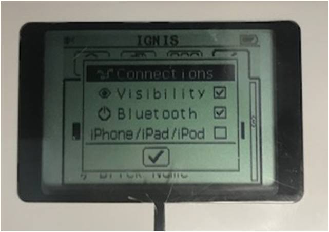
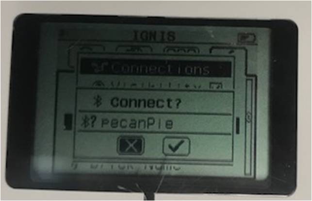
Make sure that the EV3 has Bluetooth enabled and that it is also discoverable by making sure that Visibility is turned on.  The EV3 Bluetooth menu should look like this:

Using the “old” Bluetooth button, click on “Add Device.”  The Raspberry Pi will then search for all available Bluetooth devices within range.  My EV3 is currently named IGNIS (don’t ask, my son came up with the name).

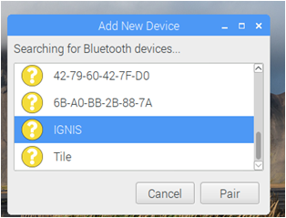
Select your EV3 device, and click “Pair.”  This will start the pairing process.  The EV3 will ask you if you want to pair to your Raspberry Pi (pecanPie, in my case).  Select yes.

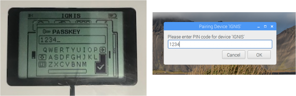
The EV3 will then prompt you for a 4-digit code.  After you enter the code in the EV3, the Raspberry Pi will ask for the same code.  The default LEGO code is simply 1234 as shown in the images below:

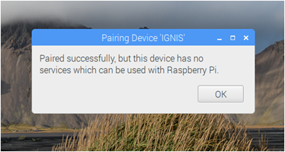
At this point, the devices should be paired, albeit not usable yet…

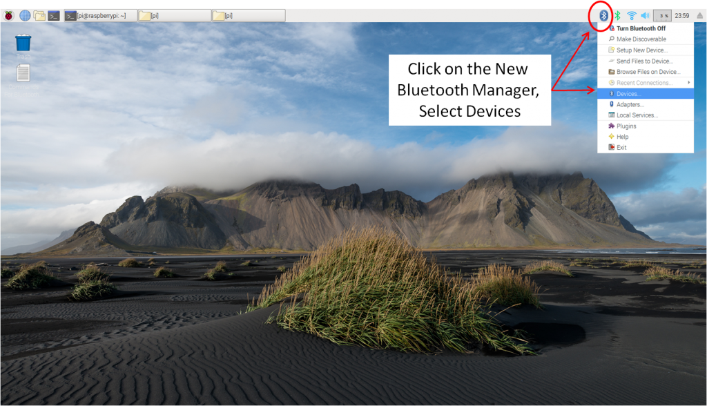
Now we need to fix the services.  Ultimately, we need to assign the Bluetooth to “rfcomm0” to make it act like a serial device.  To do this, we need to use the new Bluetooth Manager that we just installed at the top of the page.  Click on the new Bluetooth Manager, which should bring a drop down menu.  Next, click on Devices.

Clicking on Devices should result in a new window that allows you to select individual devices as shown below:

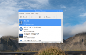
You should see your EV3 that you recently paired with your Raspberry Pi.  Select your EV3, then click on “Setup.”

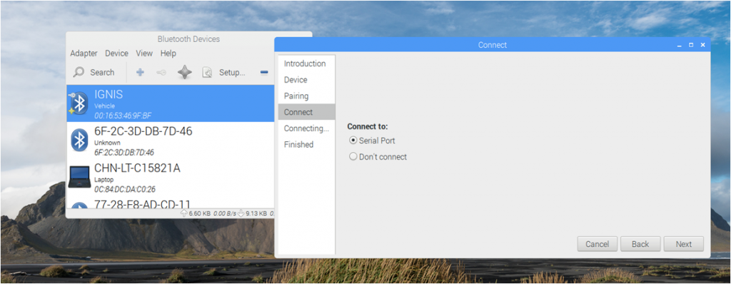
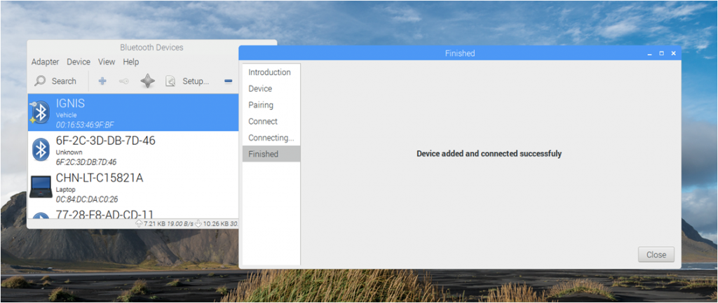
Select the option to “Connect to: Serial Port” and click on Next.  If successful, it should bring up the message that it was successfully connected.

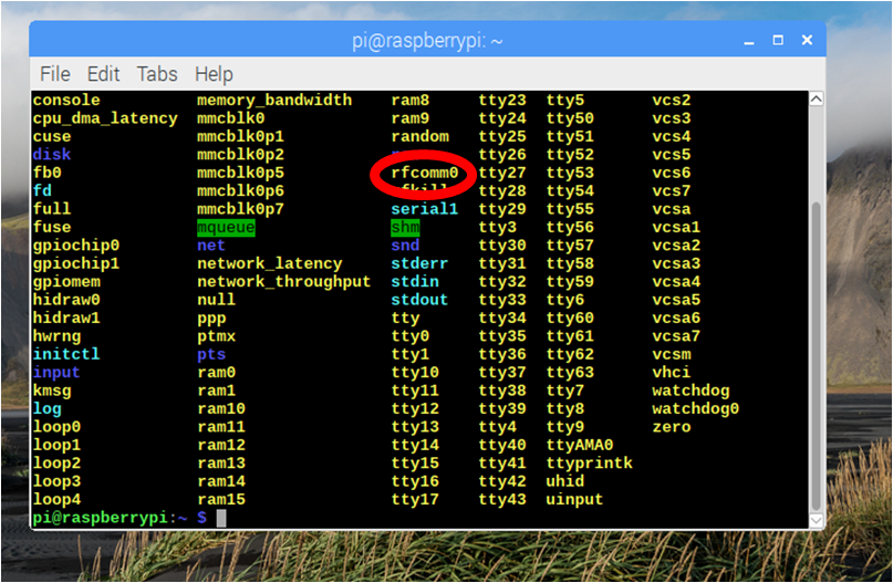
This process should have binded (bound?) the MAC id of the EV3 to the rfcomm0 serial handle.  To verify that this has happened, open a terminal window and type:

ls /dev

In this directory, you are looking for rfcomm0 (that is a zero at the end.  The font in this style makes it appear more like the letter o…).  If rfcomm0 is not listed, then something went wrong and the Bluetooth is not associated with a serial connection.  If it is not there, don’t bother proceeding as you would need to fix the problem if any of the Python code is to work.


Assuming that everything went well, you can then use the links shown at the beginning of this page to write your EV3 program and Python program on your Raspberry Pi to send messages back and forth.  The next portion covers an example of sending a message, and receiving a message.  Note that I did not write any of the Bluetooth interface code, and probably cannot answer any questions regarding it.  I’m using the Python code from:

http://www.geekdroppings.com/2018/01/21/raspberry-pi-and-the-lego-ev3-connected-by-bluetooth/

for all of the Bluetooth formatting, header formation, etc.  The author of the above link, Maksym Shyte, did a great job setting these functions up and they do work.

For our example, we will send a text message of “Can you hear me?” from the Raspberry Pi to the EV3.  Once the EV3 receives the message, it will wait for the user to press the center button, then send a message back of a Boolean value of True.

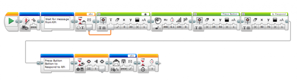
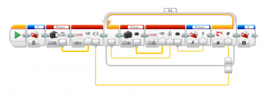
EV3-G does a terrible job of allowing meaningful comments within a program, so here is a step-by-step description of the blocks:

  1. Initialize the connection with our Raspberry Pi.  This is necessary for all Bluetooth messaging.  Make sure the name matches what you set up in the /etc/machine-info file.  In my case, it’s called pecanPie.
  2. The next step is to wait for a Bluetooth message with a message title of ‘abc.’  You can use whatever you want, but the default is simply ‘abc.’  If you change this, you will have to modify the python code as it’s currently set up to send to abc.  This block simply waits until you receive any message with this title.  The type of the message is Text, as that’s what we will send from our Raspberry Pi.
  3. Once the wait block is completed (it receives the message), we print the contents of the text on the EV3 display and make a not so pleasant beep to wake up the user.
  4. We then prompt the user to press the button to response with some more display blocks.
  5. On the second line, there is a wait block that waits until the user presses the button.
  6. The EV3 then sends a Bluetooth message of Logic value of True to pecanPie.
  7. The last delay of 1 s is not necessary.  It just stops the program from ending as abruptly.

The Python program that I used is below.  Again, credit to Maksym Shyte for the functions as I simply copy/pasted from the geekdroppings post (link was provided above).

#! /usr/bin/env python3
import struct
import enum
import serial
import time

        
def printMessage(s):
    return ' '.join("{:02x}".format(c) for c in s)

class MessageType(enum.Enum):
    Text = 0
    Numeric = 1
    Logic = 2

def decodeMessage(s, msgType):
    payloadSize = struct.unpack_from('<H', s, 0)[0]
    
    if payloadSize < 5:       # includes the mailSize
        raise BufferError('Payload size is too small')
    
    a,b,c,d = struct.unpack_from('<4B', s, 2)
    if a != 1 or b != 0 or c != 0x81 or d != 0x9e:
        raise BufferError('Header is not correct.  Expecting 01 00 81 9e')
    
    mailSize = struct.unpack_from('<B', s, 6)[0]
    
    if payloadSize < (5 + mailSize):  # includes the valueSize
        raise BufferError('Payload size is too small')
    
    mailBytes = struct.unpack_from('<' + str(mailSize) + 's', s, 7)[0]
    mail = mailBytes.decode('ascii')[:-1]
    
    valueSize = struct.unpack_from('<H', s, 7 + mailSize)[0]
    if payloadSize < (7 + mailSize + valueSize):  # includes the valueSize
        raise BufferError('Payload size does not match the packet')

    if msgType == MessageType.Logic:
        if valueSize != 1:
            raise BufferError('Value size is not one byte required for Logic Type')
        valueBytes = struct.unpack_from('<B', s, 9 + mailSize)[0]
        value = True if valueBytes != 0 else False
    elif msgType == MessageType.Numeric:
        if valueSize != 4:
            raise BufferError('Value size is not four bytes required for Numeric Type')
        value = struct.unpack_from('<f', s, 9 + mailSize)[0]
    else:
        valueBytes = struct.unpack_from('<' + str(valueSize) + 's', s, 9 + mailSize)[0] value = valueBytes.decode('ascii')[:-1] remnant = None if len(s) > (payloadSize + 2):
        remnant = s[(payloadSize) + 2:]
        
    return (mail, value, remnant)

def encodeMessage(msgType, mail, value):
    mail = mail + '\x00'
    mailBytes = mail.encode('ascii') 
    mailSize = len(mailBytes)
    fmt = '<H4BB' + str(mailSize) + 'sH'
    
    if msgType == MessageType.Logic:
        valueSize = 1
        valueBytes = 1 if value is True else 0
        fmt += 'B'
    elif msgType == MessageType.Numeric:
        valueSize = 4
        valueBytes = float(value)
        fmt += 'f'
    else:
        value = value + '\x00'
        valueBytes = value.encode('ascii')
        valueSize = len(valueBytes)
        fmt += str(valueSize) + 's'
    
    payloadSize = 7 + mailSize + valueSize
    s = struct.pack(fmt, payloadSize, 0x01, 0x00, 0x81, 0x9e, mailSize, mailBytes, valueSize, valueBytes)
    return s

if __name__ == "__main__":
    #Setup Serial Port
    EV3 = serial.Serial('/dev/rfcomm0')

    #-----Sending a message------
    #s is the message we want to send.  The encodeMessage sets up the
    #correct payload, sets up the Message Title, stuffs the bytes correctly, etc.
    s = encodeMessage(MessageType.Text, 'abc', 'Can you Hear Me?')
    #this next print is optional.  It just shows the full payload on the display.
    print('Sending the following message\n')
    print(printMessage(s))
    #the next line write the message to the bluetooth port and sends the command.  
    EV3.write(s)
    time.sleep(1)

    #-----Receiving a Message----
    print('Listening for a message, press CTRL-C to quite.\n')
    messageReceived = False
    while not messageReceived:
        n=EV3.inWaiting()
        if n!= 0:
            s=EV3.read(n)
            print(s)
            mail,value,s=decodeMessage(s,MessageType.Logic)
            print(mail,value)
            messageReceived = True
        else:
            time.sleep(0.1)
        
    EV3.close()   

To run this, start by running the EV3 program first as the EV3 simply waits for a message.  If you run the RPi/Python first, it will send a message, but the EV3 program won’t be running to receive it.  Below is a screen shot of the output of the program.

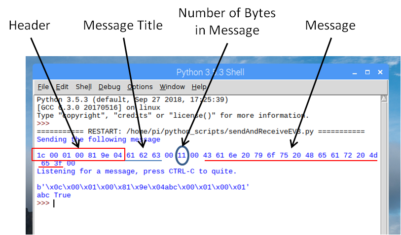
When the program sends a message, it outputs the contents of the encoded message on the display.  Note that this step is optional, but does allow one to actually see what the encoding of the message is like.  All of these pairs of numbers are single bytes, express in hexadecimal.  The first 7 bytes are the payload header information.  The next 3 bytes is the message title, or ‘abc.’  These are the ASCII values expressed in hex (a = 0x62, b = 0x63, c = 0x64).  The next byte simply separates the value for the number of bytes in the message (0x11 bytes, or 16 bytes+1).  The last group of bytes is the message itself.  They are the 16 characters in the message, “Can you Hear Me?” expressed as ASCII codes in hex values.

The returned message is also printed out, both as the raw format, plus as the just the message title and message content.

There is a lot more that can be done with this.  For example, there is no error checking to see if messages are actually received.  I also have not tested any of this for floating point numbers, etc.  The primary purpose of this blog post was to document the actual connection process between the EV3 to the Raspberry Pi and demonstrate some simple examples.  I’m hoping in the future I can return to this and establish a more robust and higher level module for communicating between the two platforms.

Posted in Robotics | Tagged , , | 3 Comments

Zumo 32U4 Synchronize Motor

I received a recent question on how to make the Zumo drive straight.  There are a few ways to do this, but the easiest way is to synchronize the motors.  In this post, I’ll briefly discuss a simple method to slave the right motor off of the left motor.  In this case, the right motor will dynamically adjust the power so that the encoder counts on the right motor match the left motor.  As a test, you can hold the left track to slow it down, and this should slow down the right track automatically.  Note that this doesn’t work the other way around.  That would take a slightly more complicated program, and I’ll try to cover that in a later post.

The main difficulty with the Zumo not going straight is due to the fact that we are using unregulated motor commands.  No two motors are ever assembled perfectly equal.  In addition, there are minor differences in friction in the gear boxes, the axles, etc.  As a result, we tell the motors to use the same power settings, and the H-bridges deliver the correct power settings, but the motors respond slightly differently.

To overcome this, we need to measure the values of the encoders as the robot is driving, and adjust the power to the right motor to force the encoders to be equal.  The basic flow would be:

  • Reset the encoders.
  • Set the power levels of the motors to an initial guess.
  • Do the following:
    • Measure the left and right encoders values.
    • Calculate the error between the two encoders (error = left encoder – right encoder).
    • Calculate a correction factor (Kp*error where Kp is a proportional gain value).
    • Modify the right motor power value (right power = initial power + correction factor).
    • Apply the modified motor power values to the setSpeed of the motors.
    • Repeat this until an end condition is met.

However, even this may not have the Zumo go perfectly straight due to minor differences in wheel diameters and track thickness.  Therefore, I added a fudge factor for calculating the error, called STRAIGHTFACTOR.  This should be adjusted for very minor values.  Default should be 1, but you may need to tweak it somewhere between 0.9 and 1.1 depending on the robot.

#include <Zumo32U4.h>
Zumo32U4Encoders encoders;
Zumo32U4Motors motors;
Zumo32U4LCD lcd;
Zumo32U4ButtonA buttonA;

#define SPEED 200
#define DISTANCE 2000
#define Kp 1
#define STRAIGHTFACTOR 1  // Adjust this to correct for minor curve.  Should be in the 0.9 to 1.1 range

void setup() {
}

void loop() {
  int currentSpeedLeft=SPEED;
  int currentSpeedRight=SPEED;
  int error;
  int correction;

  // Start Sequence - Wait for Button
  lcd.print("Press A");
  motors.setSpeeds(0, 0);
  buttonA.waitForButton();
  lcd.clear();
  delay(200);
  
  int countsLeft = encoders.getCountsAndResetLeft();
  int countsRight = encoders.getCountsAndResetRight();

  motors.setSpeeds(currentSpeedLeft,currentSpeedRight);
  do {
    countsLeft = encoders.getCountsLeft();
    countsRight = encoders.getCountsRight();
    error = countsLeft-STRAIGHTFACTOR*countsRight;
    correction = Kp*error;
    currentSpeedRight = SPEED + correction;
    motors.setSpeeds(currentSpeedLeft,currentSpeedRight);
  }  while(countsLeft<DISTANCE&&countsRight<DISTANCE);
  motors.setSpeeds(0,0);
} 

The above example sets the left motor to a speed of 200, then modifies the speed of the right motor so that the error between the two encoders is reduced to zero.  I had the loop exit condition be 2000 encoder counts, but this can be modified to go any distance, or even use light sensors to exit the loop.  I was rather explicit with the math.  Much can be simplified to some thing like:

currentSpeed Right = SPEED + Kp*(encoders.getCountsLeft() - encoders.getCountsRight()); 

All this does is save a couple variables and a few lines of code and is not necessary.

Posted in Robotics | Tagged , , | Comments Off on Zumo 32U4 Synchronize Motor

LEGO EV3 – Saving an Array to a File

I was recently asked in a forum on how to save an array from the EV3 to a file.  Imagine you are taking data with a sensor, then storing the sequential measurements in an array, and you would like to analyze this data.  You could use the data logging feature, but let’s say you wanted to include this option in a program.  This came up for one of my WRO teams in 2015 where they were trying to scan the map legend as fast as possible.  The method that they used to develop an algorithm was to read the data as fast as possible, store it in an array, then save it as a file.  After that, they downloaded the data and developed filtering and sampling methods using Excel.  This allowed them to visually look at the data as they were developing the algorithm.  Later, they left the code in the program so that they could go back and look at the data if the robot failed to interpret the data correctly.  This gave them the option to determine what went wrong, and how to fix it.

Anyway, the EV3 does not deal with arrays particularly gracefully.  Further, it deals with exporting files with about as much grace.  The method that we used was simply:

  1. Issue a delete file command for the filename you intend to use.  If you don’t, the write data to a file simply appends, and it would be appending to an old file (if one exists by the same name).
  2. Read the length of the array.  Since our measurements were based on taking as many readings as possible, the length of the array varied from run to run, and if you attempt to access an array element longer than the array is, the EV3 crashes and does wonderful unpredictable things.
  3. Setup a loop to run for a specific number of iterations.  The number of iterations is the length of the array.
  4. Within the loop, perform the following steps:
    1. Read the array at the index value of the current loop iteration.
    2. Use the file access command to write the data to a file.  Note that the file names all through this need to be the same.  This appends the data to the end of the file.
    3. Iterate the loop for the number of times that equals the length of the array.
  5. After the loop completes, close the file.

An example in EV3-G is shown below.  This was copied from a MyBlock, so it assumes that the array of data named MeasuredData already exists, and is filled with data.

Posted in Robotics | Tagged , , | Comments Off on LEGO EV3 – Saving an Array to a File

Motor Regulation: Part 2 – Using a P-Controller to Regulate Rotational Velocity

In the last post, we calculated the rotational velocity of the motor.  In this post, we will begin applying feedback to regulate the motor rotational velocity with a simple P-controller.  Like line following, a P, or proportional, feedback method is used to apply corrections to the power value.  As a review of P-controllers, the basic process is:

  1. Measure the value you want to control.
  2. Calculate the error (error = value – target value).
  3. Calculate the correction (correction = Kp x error).
  4. Apply the correction.

This is no different than with line following, but we will be using rotational velocity rather than the light sensor reading.  We could start at 0 power and ramp up with the rate of the P-controller, but that is a bit slow.  For the open loop condition, the rotational velocity was approximately the motor power divided by 10.  Let’s use that as the starting value.  The program below follows the basic flow of:

  1. Assumes a starting power.
  2. At a determined interval of 10 ms, it performs the following steps:
    1. Samples the velocity.
    2. Calculates the error.
    3. Calculates the correction factor.
    4. Updates the power setting.
  3. Exits the loop after a certain number of encoder counts.

Like before, I have the data of the velocity sent to the serial monitor in {{time, velocity},{…, …}} format to make plotting easier in Mathematica.  If you want to use Excel, you can simply remove the formatting and add tabs.

#include <Zumo32U4.h>
Zumo32U4Encoders encoders;
Zumo32U4Motors motors;
Zumo32U4LCD lcd;
Zumo32U4ButtonA buttonA;

#define dT_MOTOR 10
#define Kp_MOTOR 0.06
#define MOTOR_VEL 2000

void setup() {
  Serial.begin(115200); // initialize Serial communication
  while(!Serial);
  lcd.clear();
}

void loop() {
  int newPosition, oldPosition;
  int vel;
  int error;
  int newPower;
  unsigned long startTime, lastSampleTime;

  lcd.print("Press A");
  buttonA.waitForButton();
  lcd.clear();
  delay(200);
  startTime=millis();
  lastSampleTime=millis();
  newPower=MOTOR_VEL/10;
  oldPosition=encoders.getCountsAndResetLeft();
  Serial.print("{{0,");
  Serial.print("0},");
  motors.setSpeeds(newPower,0);
  do {
    if(millis()-lastSampleTime>dT_MOTOR-1) {
      newPosition=encoders.getCountsLeft();
      vel=(newPosition-oldPosition)*1000/dT_MOTOR;
      error=vel-MOTOR_VEL;
      oldPosition=newPosition;
      lastSampleTime=millis();
      newPower=newPower-Kp_MOTOR*error;
      motors.setSpeeds(newPower,0);
      Serial.print("{");
      Serial.print(millis()-startTime);
      Serial.print(",");
      Serial.print(vel);
      Serial.print("},");
    }
  } while(encoders.getCountsLeft()<2000);
  motors.setSpeeds(0,0);
} 

Using a value of Kp_MOTOR = 0.4, I got the following results:

rot-vel-kp0p4

In this case, the velocity setting of 4000 never quite reaches the target.  This is due to driving the robot with only one tread, and the other tread is rubbing against the table.  For the other values of velocity, there is a little overshoot and they settle relatively quickly.  The most exciting part about this is that I can hold the wheel and feel the power increase to attempt to maintain a constant rotational velocity.  I can also drive this at low speeds now with the robot stalling.

As another test, I increased the gain to 0.6.

rot-vel-kp0p6

The results are not very different, but the gain difference was minor.  At this point, you can see slightly faster rise times, but more overshoot and a dampened oscillation.  If I look at the actual power levels calculated in the program, I get this:

power-kp0p6

Keep in mind that anything above 400 is automatically limited to 400 in the library function for setting the speed.  At a speed of 4000, we are not able to drive the motors enough and the regulation fails.  However, at lower rotational velocity levels, you can see how the power is initially driven higher, then reduced in order to maintain a constant speed.

At this point, I could tweak the Kp value to get the best response for a given speed, but I’d rather wait until the next post and add a full PID controller.  The PID should work over a broader range of power values with a faster response and cleaner settling.


Posted in Robotics | Tagged , | Comments Off on Motor Regulation: Part 2 – Using a P-Controller to Regulate Rotational Velocity

Motor Regulation: Part 1 – Calculate Rotational Velocity

The next several posts are going to deal with writing functions for regulated motor blocks.  So far, everything shown in this blog for the Zumo uses unregulated motors.  At some point, having regulated and synchronized motors will be necessary for precise navigation.  Since I have some time on my hands now, I figured I’d begin tackling it.

First of all, what is motor regulation?  In this case, I’m referring to a method of maintaining constant rotational velocity, as opposed to a constant power applied to the motors.  The actual power applied to the motor will fluctuate to maintain a specific rotational velocity.

Why do we need motor regulation?  Well, there are several reasons, and I’m only going to touch on a few.  First of all, if you look at the schematic, the H-bridges that drive the two motors operate off of the battery voltage, not the voltage after the motor regulator.  Therefore, as the battery voltage changes, the velocity of the robot changes.  Another reason is to deal with motional resistance better.  Let’s say the robot is driving at a speed of 200, then it hits an object.  The robot will naturally slow down and the power will stay at 200.  However, if using a regulated motor function, the robot measures the rotational velocity of the wheels, notices that it slows down, and increase the power to maintain a constant rotational velocity (up to the limit).  Another great reason to use regulated motor functions is for low velocity, precise movement.  If you want the robot to move very slowly, it often will stall under lower power levels.  Motor regulation will dynamically adjust the power to allow it to move precisely at low velocities.

This topic will be split over several posts.  The content is written primarily for my middle school robotics kids.  People who understand control theory will think it’s too easy, people using the Zumo after using the EV3 may think it’s overly complicated.  If you have any questions, please send me a note through the “Contact Me” tab and I’d be happy to help you out.

This post will deal first with setting a power level, and measuring the rotational velocity.  In all cases, I’m leaving the velocity in terms of encoder counts on my 75:1 Zumo robot.  Velocity is simply the change of encoder counts divided by the change in time.  I can control the change in time by setting how fast I sample the measurements.  For reasons that will become clear later the regulated motor topic, we don’t want to sample too fast.  For now, let’s sample at about 10 ms.

The code below turns the motors on at a power of 300 for a short distance, calculates the rotational velocity, and outputs the velocity vs. time to the serial monitor.  I used the output format of “{time,velocity}” to be compatible with Mathematica, which I use for plotting the data.

#include <Zumo32U4.h>

Zumo32U4Encoders encoders;
Zumo32U4Motors motors;
Zumo32U4LCD lcd;
Zumo32U4ButtonA buttonA;

#define dT_MOTOR 10       //Sample time for velocity calculation
#define MOTOR_POWER 300   //Motor power
void setup() {
  Serial.begin(115200); // initialize Serial communication
  while(!Serial);
  lcd.clear();
}

void loop() {
  int newPosition, oldPosition;
  int vel;
  unsigned long startTime, lastSampleTime;

  lcd.print("Press A");
  buttonA.waitForButton();
  lcd.clear();
  delay(200);

  startTime=millis();                              //Record the start time
  lastSampleTime=millis();                         //Initiallize the time of the last sample
  oldPosition=encoders.getCountsAndResetLeft();
  Serial.print("{{0,");
  Serial.print("0},");
  motors.setSpeeds(MOTOR_POWER,MOTOR_POWER);
  do {
    if(millis()-lastSampleTime>dT_MOTOR-1) {       //If current time-lastSample >= sample time....
      newPosition=encoders.getCountsLeft();
      vel=(newPosition-oldPosition)*1000/dT_MOTOR;
      oldPosition=newPosition;
      lastSampleTime=millis();
      Serial.print("{");
      Serial.print(millis()-startTime);
      Serial.print(",");
      Serial.print(vel);
      Serial.print("},");
    }
  } while(encoders.getCountsLeft()<500);
  motors.setSpeeds(0,0);
} 

The chart below shows typical data for various power levels.  Note that there is some ripple from due to rounding at the sampling times.  If I were to run the same conditions, but had the robot pushing an object, the robot would slow down considerably.  Also, notice in the plot how the rise time for the slower speeds appears fairly slow to settle.  Regulation should speed that up considerably by applying more power at the start to overcome the robot inertia.

rot-vel-from-power

In the next post, we will put the motor in a proportional feedback loop to provide a low order of regulation.

Posted in Robotics | Tagged , | Comments Off on Motor Regulation: Part 1 – Calculate Rotational Velocity

Zumo 32U4 – Using the Buttons the Select a Start Move

This post discusses one way to handle setting up the Zumo to perform one of three initial moves prior to entering the main body of the program.  If you go back a couple of posts, we discussed the simple state machine for a sumo competition.  In the setup, there was a section for the initial move.  The initial move is the first move you want your robot to make prior to entering the state machine and following a preset algorithm.  This could be a fixed move, in which case, you can ignore this post.  However, you may decide you want to have your robot do a different initial move based on how your competitor is set up, or in the case of BottleSumo, where the bottle is located.  In this case, you often don’t know these conditions until you are set up at the table, ready to go.

This post describes a way that you can use the three buttons to select a particular first move.  So far, we’ve only used the buttons to wait until you press a button.  In this case, we need to record the action we want to take, wait for a button, then take that action.

The basic flow is:

  1. Check to see if any of the three buttons are pressed.
  2. If a button is pressed, record which one.
  3. Go to step 1 if no button is pressed, if not, proceed to step 4.
  4. Wait until button A is pressed to signal the start of the match.
  5. Execute the option selected from step 2.
  6. Proceed to normal state machine.

To make it easier, I like to use the enum function to define a data type.  You cold simply use an integer to represent button A, B, and C, but why not use the actually button name?  Defining the datatype with enum is done as below:

enum ButtonChoice       // Create datatype for the button label.
{
  A,
  B,
  C
}; 

This creates a datatype  named ButtonChoice that allows values of A, B, and C.  The next step is to continuously check the buttons until one is pressed.  For this, you will need a Boolean variable to store whether or not a button has been pressed.  It gets initialized to false, as a button has not been pressed at the beginning.  As usual, I always think it is a good idea to give the user feedback by prompting on the LCD and providing beeps to know if you have pressed a button.

bool buttonPressed = false;       // Boolean whether or not a button has been pressed.
ButtonChoice buttonSelected;      // variable to store which button was pressed.

// Prompt User and Wait for Button.  Record which button is pressed.
  lcd.clear();
  lcd.gotoXY(1, 0);
  lcd.print("Press:");
  lcd.gotoXY(0, 1);
  lcd.print("A  B  C");
  do {
    if (buttonA.isPressed()) {
      buttonSelected = A;
      buttonPressed = true;
      buzzer.playFrequency(300, 200, 15);
    }
    if (buttonB.isPressed()) {
      buttonSelected = B;
      buttonPressed = true;
      buzzer.playFrequency(440, 200, 15);
    }
    if (buttonC.isPressed()) {
      buttonSelected = C;
      buttonPressed = true;
      buzzer.playFrequency(600, 200, 15);
    }
  } while (!buttonPressed); 

At this point, you’ve selected with variant you want to run, you just need to wait till you press the button to start, and run the first move.  for this example, I made the first move options very simple.  If A is pressed, the robot moves forward, if B is pressed, the robot moves backwards, and if C is pressed, the robot turns.  In practice, you probably want something more specific, like targeting a region of the table, moving out of the way, etc.

// Wait for button and execute the selection.
lcd.clear();
lcd.print("Press A");
lcd.gotoXY(0, 1);
lcd.print("to Go!");
buttonA.waitForButton();
buzzer.playFrequency(440, 50, 15);
lcd.clear();

switch (buttonSelected) {
  case A:
    lcd.print("Case A");
    motors.setSpeeds(200, 200);
    delay(1000);
    motors.setSpeeds(0, 0);
    break;
  case B:
    lcd.print("Case B");
    motors.setSpeeds(-200, -200);
    delay(1000);
    motors.setSpeeds(0, 0);
    break;
  case C:
    lcd.print("Case C");
    motors.setSpeeds(-200,200);
    delay(1000);
    motors.setSpeeds(0,0);
    break;
}  

When putting this into your sumo state machine, you will clearly have to add other items such as the initial state to start in, light sensor calibrations, initializations, etc.  Putting the whole example program together:

#include <Zumo32U4.h>
Zumo32U4LCD lcd;
Zumo32U4Motors motors;
Zumo32U4ButtonA buttonA;
Zumo32U4ButtonB buttonB;
Zumo32U4ButtonC buttonC;
Zumo32U4Buzzer buzzer;

enum ButtonChoice       // Create datatype for the button label.
{
  A,
  B,
  C
};

void setup() {
  bool buttonPressed = false;       // Boolean whether or not a button has been pressed.
  ButtonChoice buttonSelected;      // variable to store which button was pressed.

  // Prompt User and Wait for Button.  Record which button is pressed. 
  lcd.clear(); 
  lcd.gotoXY(1, 0); 
  lcd.print("Press:"); 
  lcd.gotoXY(0, 1); 
  lcd.print("A  B  C"); 
  do { 
    if (buttonA.isPressed()) { 
      buttonSelected = A; 
      buttonPressed = true; 
      buzzer.playFrequency(300, 200, 15); 
    } 
    if (buttonB.isPressed()) { 
      buttonSelected = B; 
      buttonPressed = true; 
      buzzer.playFrequency(440, 200, 15); 
    } 
    if (buttonC.isPressed()) { 
      buttonSelected = C; 
      buttonPressed = true; 
      buzzer.playFrequency(600, 200, 15); 
    } 
  } while (!buttonPressed); 
  delay(500);   
  
  // Wait for button and execute the selection. 
  lcd.clear(); 
  lcd.print("Press A"); 
  lcd.gotoXY(0, 1); 
  lcd.print("to Go!"); 
  buttonA.waitForButton(); 
  buzzer.playFrequency(440, 50, 15); 
  lcd.clear(); 
  
  switch (buttonSelected) { 
    case A: 
      lcd.print("Case A"); 
      motors.setSpeeds(200, 200); 
      delay(1000); 
      motors.setSpeeds(0, 0); 
      break; 
    case B: 
      lcd.print("Case B"); 
      motors.setSpeeds(-200, -200); 
      delay(1000); 
      motors.setSpeeds(0, 0); 
      break;     
    case C: 
      lcd.print("Case C"); 
      motors.setSpeeds(-200,200); 
      delay(1000); 
      motors.setSpeeds(0,0); 
      break; 
  } 
} 

void loop() { 
  // Put the rest of the state machine here. 
} 
 In addition to the three options, you could make the menu go deeper into other options.  It might be something like A means go forward, then have another menu for how far forward.  This would essentially allow you to call an audible at the start time to keep your opponents guessing what your robot will do.
Posted in Robotics | Tagged , , | Comments Off on Zumo 32U4 – Using the Buttons the Select a Start Move

Read Data from the VL53L0X ToF Sensor Mounted on the Zumo 32U4

In this post, we will write a short program to read the data from the VL53L0X and display the data to the Serial Monitor.  As usual, we will need the Zumo32U4 library, but we will also need the I2C library (Wire.h) and the VL53L0X library (VL53L0X.h).  Wire should be built included with the Arduino distribution.  However, you will probably need to download and install VL53L0X from the Manage Libraries menu.  In addition to including the libraries, we need to create an instance of the time of flight sensor, similar to how we do the same for the Zumo buzzer, buttons, motors, etc.  The code for the libraries and creating an instance of the ToF sensor object are shown below:

#include <Zumo32U4.h>
#include <Wire.h>
#include <VL53L0X.h>

VL53L0X tofsensor;
Zumo32U4ButtonA buttonA;
Zumo32U4Buzzer buzzer; 

Within the setup(), we need to initialize a few things.  The first thing we need to do is to initialize the I2C bus.  Without telling the Zumo that we are going to use the I2C bus, the microcontroller won’t know how to communicate with the sensor.  This is simply done with:

Wire.begin(); 

The next step is to initialize the sensor, and tell the sensor that we want to use it in continuous operation (sensor stays active and doesn’t restart and calibrate every measurement).

tofsensor.init();
tofsensor.startContinuous(); 

At this point, the sensor is ready and we just need to issue the command to take the measurement with:

tofsensor.readRangeContinuousMillimeters(); 

Putting everything together and outputting the data to the serial monitor:

#include <Zumo32U4.h>
#include <Wire.h>
#include <VL53L0X.h>

VL53L0X tofsensor;
Zumo32U4ButtonA buttonA;
Zumo32U4Buzzer buzzer;

void setup()
{
  Serial.begin(115200);
  Wire.begin();
  tofsensor.init();
  buttonA.waitForButton();
  buzzer.playFrequency(440, 200, 15);
  tofsensor.startContinuous();
}

void loop()
{
  int distance;
  distance=tofsensor.readRangeContinuousMillimeters();
  Serial.println(distance);
  delay(20);
} 

Note that this uses the default settings for the ToF sensor.  There are a lot of settings that can be tweaked to either maximize range, accuracy, or measurement time.  In default mode, I get about 800 mm reliably with consistent accuracy and 33 ms read times.  I’ll try to write a post soon regarding the various options you can choose to configure the sensor.

Another item to note is that the datasheet does not specify the beamwidth of the sensor system (combined VCSEL and detection APD).  However, one of the prints shows a 25 degree cone.  This would make it not usable for a robot close to the ground like a Zumo.  I took some measurements and I’m seeing about 3-4 degrees, which is quite narrow.
Posted in Robotics | Tagged , | 3 Comments

Attaching a VL53L0X Breakout Board to Zumo for Accurate Range Finding

The IR sensors on the Zumo 32U4 left us wanting with a desire for a lot more range.  We came across the VL53L0X Time-of-Flight range finding module.  The VL53L0X is capable of up to 2 m range with mm level resolution, and boasts that it is insensitive to ambient lighting conditions, angle of target object, and reflectivity of target object.  Seems too good to be true, so we tried it out.  This post discusses how to hook up a breakout board (manufactured by Pololu) to the Zumo 32U4 and how to take data.

The time of flight sensor uses a VCSEL diode (a type of laser diode) to transmit a pulse of IR light.  The light hits an object, a small portion is reflected back, and the module uses an avalanche photodiode to detect and amplify the pulse.  The module then compares the time difference between when the pulse was sent out and when it was received to determine the range.  It’s a pretty neat module, especially considering that the speed of light is 3e8 m/s, and 1 mm resolution would mean that it can sense time differences in the 1 ps range.

0j7226-600x480

Above is an image from the Pololu website for the module and breakout board (https://www.pololu.com/product/2490).  At about $14, it is hard to beat.  The module uses a 5V I2C protocol, which makes it very easy to interface with the Zumo 32U4.  The image above shows the external connections to the board.  However, all we need to really worry about is Vin, Gnd, SDA, and SCL.

Vin is the input voltage to the module.  This particular board has a voltage regulator that can take a range of input voltages, and regulated it down to the correct level for the ToF module.  Gnd is the ground reference.  SDA and SCL are the I2C pins for Serial Data and Serial Clock.  To go into the workings of I2C is beyond the scope of this post, but all you really need to understand for now is that we need to hook these connections up to the equivalent pins on the Zumo.

zumo-i2c-connections

The above image is taken from the Zumo 32U4 pinout document from the Pololu website (https://www.pololu.com/file/0J864/zumo-32u4-pinout.pdf).  Note that the right side expansion port has ground, 5V, SDA, and SCL thru-holes that we can attached pins to.  How convenient!

img_1698

I soldered some 0.1″ pins into these thru-hole pads.  There is a nice access window in the chassis where the batteries go to allow access to the solder pads from the underside.  I also added some 2-56 stand-offs to allow me to attach a thin plywood platform to mount the sensor to the robot.

img_1699

I then built up a 4-wire harness to connect the Zumo connections to the ToF sensor pins.  You can use 6″ female-to-female jumper wire as well if you don’t want to build a custom wire harness.

img_1701

The picture above shows the ToF sensor mounted to the wood platform with the wire harness attached.  The sensor breakout board has 2 mounting holes where I used 2-56 socket head screws to mount the sensor to the platform.  Note that I could not use a washer as it interferes with some of the components on the board.

The next post will discuss how to write a program to read from the sensor as well as optional methods of configuring the sensor.

Posted in Robotics | Tagged , | Comments Off on Attaching a VL53L0X Breakout Board to Zumo for Accurate Range Finding

Simplified Sumo State Machine for Zumo

This post will talk about a simple state machine that could be used for robot sumo.  The target here is the Robofest Senior BottleSumo rules, so the state machine is adapted for long searching on large tables.  If you want to do international sumo rules, the state diagram would look a bit different.

A state machine is a device that can be in a specific condition based on previous conditions and the current value of its inputs.  One of the easiest ways to describe the behavior of a state machine is through a state diagram.  A state diagram depicts each state with a circle, then connects the states with arrows to show how the device can transfer between different states, and the conditions required for the device to change states.  You can think of it a bit like a Furby where each behavior the Furby has is a particular state.  There are things you can do to the Furby that will cause it to go from one state to another.

A very basic BottleSumo state diagram is shown below.  Note that this is just the beginning.  Personally, I’d add many other states and transitions between states to optimize performance.


simplestatediagram

A description of each state found below:

  • Start – Initialize global variables, initialize sensors, perform a light sensor calibration, etc.  This would be the stuff done in the setup().
  • Initial Move – The BottleSumo rules have a specific start condition.  This state would perform the unknown start condition, and maneuver the robot to a point on the table where it can really begin the state machine sequence.  Since this is performed only once, it also would be in the setup().
  • Scan – Pretty much what it says.  Look around for targets.  If the robot sees a target, transition to Rotate to Target.  If the robot sees nothing, the robot should go for a walk.
  • Rotate to Target – This assumes that a target is in site, this state rotates to face the target.  After this is complete, the robot should charge the target.
  • Charge the Target – Ramming Speed!  You are currently facing the target, now is the time to charge it.  This state drives the robot hard until it sees the edge of the table.
  • Recover from Edge – The only way that the robot enters this state is having driven to an edge of the table.  At this point, you could square to the edge, backup, rotate, then go into Scan again.
  • Wander – Basically just going for a walk around the table.  This diagram assumes you are wandering at a slower speed, and monitoring the downward facing light sensors and proximity sensors.  If you wander to an edge of the table, you Recover from Edge.  If you see a target while wandering, you Rotate to Target.

As I said above, this is really just the beginning.  You can add a lot more complexity as you see fit.  To create a state machine, it is very useful to create a datatype that defines the states.  You could simply assign each state a number and refer to the states as integers.  However, I’m old…. It is much easier to create a datatype that uses the state name.  To do this, you need to use the enum command.

enum State
{
  stateScanning,            // Robot scans from static position.
  stateWander,              // Robot wanders around.  
  stateRotate2Target,       // Assumes target is found, will rotate to largest prox value.
  stateChargeTarget,        // Charges a target.  
  stateEdgeRecovery         // Recovers from finding an edge.
}; 

This creates a new datatype called “State” that can consist of only the values listed.  This allows us to declare a variable of this datatype later that will store the current value of the state.  You can also create variables that can store previous values of the state as well.   Note that I did not include the states for Start and Initial Movement.  These are simple enough and can be handled in the setup() individually.

The next thing we need to do is to create the variable of datatype State, and store the first state of the robot that we want to execute once the loop() begins.  We can do this with the following statement:

State currentState = stateScanning;        // Declare and initialize the state variable of type State 

This command creates a variable named “currentState” that is type State (uppercase s), and we are assigning that variable the value of stateScanning, which is the state we want to be in when we enter loop() for the first time.

You would then write the setup() function, which does all the normal stuff we would do such as initialize sensors, light sensor calibrate, etc, but then we would add the start condition and the first move.  After the setup is complete, we begin the loop().  Each time through the loop, the robot needs to look at the value of the variable state, execute the commands associated with the value, change states, then begin the loop again (which should be under a new state).  This can be done easily with the switch case command.  Details for this particular command can be found at:

https://www.arduino.cc/en/Reference/SwitchCase

Below is an example, with a lot of the functional code for each state removed, for the basic state machine described above.

#include <Zumo32U4.h>
Zumo32U4LCD lcd;
Zumo32U4ProximitySensors proxSensors;
Zumo32U4ButtonA buttonA;
Zumo32U4Motors motors;
Zumo32U4Encoders encoders;
Zumo32U4Buzzer buzzer;
Zumo32U4LineSensors lineSensors;

// setup possible values of the robot states
enum State
{
  stateScanning,            // Robot scans from static position.  
  stateWander,              // Robot wanders around.  
  stateRotate2Target,       // Assumes target is found, will rotate to largest prox value
  stateChargeTarget,        // Charges a target. 
  stateEdgeRecovery         // Recovers from finding an edge.
};

// Global Variables
unsigned int lineSensorValues[3];   // line sensor values.  Array of [left, middle, right]
State currentState = stateScanning;        // Declare and initialize the state variable of type State

void setup() {
  proxSensors.initThreeSensors();
  lineSensors.initThreeSensors();
  calLightSensors(5);
  
  // Wait for Start
  lcd.clear();
  lcd.print("Press A");
  buttonA.waitForButton();
  lcd.clear();
  // Add Code for Start Condition Here
  // Add Code for the First Move Here
}

void loop() {

  switch (currentState) {
    case stateScanning:
      {
        // Add code for the scanning step
        if(ADD CONDITIONAL FOR FINDING A TARGET) {
          currentState=stateRotate2Target;
        } else {
          currentState=stateWander;
        }
      }
      break;

   case stateRotate2Target:
      {
        //Add code for rotating to face a target  
        currentState=stateChargeTarget;
      }
      break;
    case stateChargeTarget:
      {
        // Add code for charging a target
        currentState=stateEdgeRecovery;
      }
      break;

    case stateEdgeRecovery:
      {
        // Add code for recovering from hitting the edge of the table.
        currentState=stateScanning;
      }
      break;

    case stateWander:
      {
        // Add code for wander routine
        if(ADD CONDITION FOR IF THE ROBOT IS AT THE EDGE OF TABLE) {
          currentState=stateEdgeRecovery;
        } else if(ADD CONDITION FOR FINDING A TARGET) {
          currentState=stateRotate2Target;
        } 
      }
      break;
  } // This ends the switch case block
} 

There are a lot of commented out sections that should be filled in for the behavior or each state.  Also, the conditions for some of the state changes are clearly not detailed.  However, this should give you the starting point for putting stuff together.  I would encourage you to make separate test programs for the various states prior to putting them in the full state machine.  This allows you to create and test each state by themselves prior to dealing with transitioning between many states.

Posted in Robotics | Tagged , , | 1 Comment

Zumo 32U4 Unregulated, Unsynchronized Motor Steer Block

This post brings us back to motion and navigation.  One of the goals was to make the Zumo behave a bit more like a LEGO EV3.  The EV3 has these very useful MoveSteer block.  While this seems like a very simplistic block when you use it, there is a lot of information under the hood of the block that the user doesn’t see.  A few highlights of the MoveSteer block are:

  • The block automatically calculates the power distribution to each motor for values of steering between -100 and +100, increments of 1.
  • The block counts the encoder pulses, and automatically determines to use the left encoder when turning right and the right encoder when turning left in order to select the encoder the with most amount of travel (maximizes accuracy).
  • It uses a PID control to regulate the rotational velocity of the under any load within valid range.  This is a very complicated process with a lot of calculations.  Basically, the value that you enter for power is actually proportional to rotational velocity.  The brick dynamically measures the rotational velocity and adjusts the power to each motor to maintain a constant velocity.
  • Wheel synchronization.  The brick calculates the differences in rotation between the two motors and adjusts the power to attempt to keep the motors in synchronization.

The purpose of this post is to look at the first two items in this list.  We will hopefully get to the other two, but that will be the topics of later posts.  First of all, let’s talk about the power distribution to the motors.  After logging the power values to the motors under several conditions, I mapped the relative power to each motor for adjusting the turn value from -100 to 100.  This is shown in the plot below.

motor-power-values

As expected, if the turn value is 0, both motors are at the same power.  If the turn value is -100, the right motor is at the power value entered, and the left motor is at the negative value of the power level entered, and the opposite for the value of 100.  Of course, there are all of the values in between as well.

Another way of saying this is:

  • If the turn value is less than 0, then the right motor is the target speed, and the left motor is the target speed times (turn value + 50)/50, or for those that like it in slope/intercept, it is 1/50*(turn value)+1.
  • If the turn value is 0 or greater, then the left motor is the target speed, and the right motor is the target speed times (turn value-50)/(-50), or -1/50*(turn value)+1.

In Arduino, it is simply:

if(turnDirection>0) {
  targetSpeedLeft=targetSpeed;
  targetSpeedRight=targetSpeed*(turnDirection-50)/(-50.0);
}
else {
  targetSpeedRight=targetSpeed;
  targetSpeedLeft=targetSpeed*(turnDirection+50)/(50.0);
} 

Note that we do not have to actually evaluate if turnDirection<0 as it will be the default case if turnDirection is not greater than 0.   Once the weighting of the speed it done, you can set the motors:

motors.setSpeeds(targetSpeedLeft,targetSpeedRight); 

You can drive the motors based on the encoder counts just like we previously did in the post regarding how to read the encoders. However, they will be different if the robot is turning. Like the EV3, we would like to base the movement on the encoder that moves the most, or the one on the outside of the turn. This is shown below:

if (turnDirection>=0) 
  {
    do {
      countsLeft = encoders.getCountsLeft();
    } while (abs(countsLeft)<abs(enCounts));
  } else {
    do {
      countsRight = encoders.getCountsRight();      
    } while (abs(countsRight)<abs(enCounts));
  } 

The complete function for driving a specific number of encoder pulses for a specific turn direction is given below:

void unRegMoveSteer(int targetSpeed, int turnDirection, int enCounts) {
  int countsLeft; 
  int countsRight;
  int targetSpeedLeft;
  int targetSpeedRight;
 
  if(turnDirection>0) {
    targetSpeedLeft=targetSpeed;
    targetSpeedRight=targetSpeed*(turnDirection-50)/(-50.0);
  }
  else {
    targetSpeedRight=targetSpeed;
    targetSpeedLeft=targetSpeed*(turnDirection+50)/(50.0);
  }
  motors.setSpeeds(targetSpeedLeft,targetSpeedRight);
  if (turnDirection>=0) 
  {
    do {
      countsLeft = encoders.getCountsLeft();
    } while (abs(countsLeft)<abs(enCounts));
  } else {
    do {
      countsRight = encoders.getCountsRight();      
    } while (abs(countsRight)<abs(enCounts));
  }    
} 

You can use the function in the program as shown below:

#include <Zumo32U4.h> 

Zumo32U4Encoders encoders;
Zumo32U4Motors motors;
Zumo32U4ButtonA buttonA;
Zumo32U4Buzzer buzzer;

void setup() {
}

void loop() {
  
  motors.setSpeeds(0,0);
  buttonA.waitForButton();   
  buzzer.playFrequency(440, 200, 15);
  delay(200);

  unRegMoveSteer(150, 0, 1000);
  motors.setSpeeds(0,0); 
} 

This will make the robot move forward at a speed of 150, turn direction of 0 (straight forward) for 1000 encoder pulses.  You can try other values and make sure that the function works under all conditions.  Note that negative encoder counts won’t actually work as we use the absolute values as the end condition for the movement.


Posted in Robotics | Tagged , , | Comments Off on Zumo 32U4 Unregulated, Unsynchronized Motor Steer Block

Zumo 32U4 Sensor Read Times

Last post had the Zumo rotate and face a target.  I’ve been working on driving towards the target in an attempt to push it off of a table like done in Sumo competitions with great success with the rare occasion that the Zumo thinks it can fly and goes right off the table.  While driving towards the target, the program performs light sensor reads and proximity sensor reads as fast as possible while driving.  I know that it won’t fall off the table with only the light sensor reads based on a previous post.  Therefore, it is hypothesized that the proximity sensor reads are fairly long operations.  This post tests that theory out.

The program below uses the Zumo timer, millis(), to time how long it takes to perform 1000 light sensor reads, and 1000 proximity sensor reads.  The time for each read is calculated by simply dividing that amount of time by 1000, and displays on the Serial Monitor.

#include <Zumo32U4.h>

Zumo32U4ProximitySensors proxSensors;
Zumo32U4ButtonA buttonA;
Zumo32U4Motors motors;
Zumo32U4Buzzer buzzer;
Zumo32U4LineSensors lineSensors;

unsigned int lineSensorValues[3];

void setup() {
  proxSensors.initThreeSensors();
  lineSensors.initThreeSensors();
  Serial.begin(115200);
}

void loop() {
  unsigned long startTime;
  unsigned long runTime;
  Serial.println("Light Sensor 1k Test");
  startTime=millis();
  for(int i=1;i<1000;i++) {
    lineSensors.read(lineSensorValues);
  }
  runTime=millis()-startTime;
  Serial.print("Time per Read: ");
  Serial.print(runTime/1000.0);
  Serial.println(" ms");

  Serial.println("Proximity Sensor 1k Test");
  startTime=millis();
  for(int i=1;i<1000;i++) {
    proxSensors.read();
  }
  runTime=millis()-startTime;
  Serial.print("Time per Read: ");
  Serial.print(runTime/1000.0);
  Serial.println(" ms");

  buttonA.waitForButton();
  buzzer.playFrequency(440, 200, 15);
} 

When I first ran this, I thought that the proximity sensor read section hung up.  It took a little over 13 s to run 1k proximity sensor reads!

Here is my output on the Serial Monitor:

Light Sensor 1k Test
Time per Read: 2.53 ms
Proximity Sensor 1k Test
Time per Read: 13.03 ms 

I was a little surprised at the light sensor reads as analog reads on an Arduino are in the order of 0.2 ms.  However, it is attempting to read three sensor and may perform some averaging.  2.5 ms is not a problem given the speed of the robot.  However, 13 ms for a proximity sensor read is way too long.  At a motor power of 400, the robot moves at 5000 encoder counts per second for a 75:1 gear ratio.  There are 909.7 counts per 360 degree of wheel rotation making the rotational velocity 1980 degrees per second.  The wheel and track is 38 mm in diameter.  That means for every 360 of rotation, the robot moves almost 120 mm.  That puts the robot velocity at 660 mm/s!  If it takes 2.53 ms to take a light sensor reading, then the robot could travel 1.7 mm during the measurement.  However, if the robot is trying to take both a light sensor array measurement and a proximity sensor measurement, the robot could move an additional 11 mm before the robot could possibly respond to the sensor input.  Add in the fact that the robot cannot instantly stop, but needs some time to turn off the motor power and let the momentum of the robot slow down, and you could potentially be off of the table!  So…. when charging an object to push it off of the table, we may want to not reading the proximity sensors, or find another way to sensor distance.

Posted in Robotics | Tagged , , , | Comments Off on Zumo 32U4 Sensor Read Times

Zumo 32U4 – Using the Proximity Sensors to Point Towards the Closest Object

Assuming you want to use the cute little Zumo for a Robot Sumo competition, you need to make the Zumo turn in the direction of the highest proximity.  This may be a competing robot, or in the case of Robofest BottleSumo, it may be a 2L bottle.  Either way, the faster you can identify and turn towards the closest object, the faster you can do something about it.  In this post, I discuss a simple way to turn to point to the closest object within the range of the proximity sensors.  There are lots of ways to do this, including the example that comes with the Zumo library.  The example is very elegant, but slightly abstract for my target audience of these blog posts.  For this post, I’ll take a very simple procedural approach.

The flow is:

  • If the left proximity sensor is the strongest, rotate counter-clockwise until the front sensor with the left LED is the strongest.
  • Else if the right proximity sensor is the strongest, rotate clockwise until the front sensor with the right LED is the strongest.
  • At this point, we know that the left or right sensor are lower than the front sensor with either LED.  Therefore, if the front with the left LED is stronger, rotate counter clockwise until the front has the same returned signal for the left and right LED’s.  Similarly, if the front with the right is stronger, rotate clockwise until the front returns the same level with both the left and the right LED’s.

The easiest way to define the last step is to use a variable named “error” which is the difference of the front with right LED minus the front with left LED.  The function for this is shown below:

void turnToStrongestProx() {
  int left,frontLeft,frontRight,right;
  int error;

  proxSensors.read();
  displayProximity();
  left=proxSensors.countsLeftWithLeftLeds();
  frontLeft=proxSensors.countsFrontWithLeftLeds();
  frontRight=proxSensors.countsFrontWithRightLeds();
  right=proxSensors.countsRightWithRightLeds();
  if(left>frontLeft&&left>frontRight&&left>=right) {
    motors.setSpeeds(-TURN_SPEED,TURN_SPEED);
    do {
      proxSensors.read();
      displayProximity();
    } while (proxSensors.countsFrontWithLeftLeds()<left);
  }  else if(right>frontLeft&&right>frontRight&&right>left) {
    motors.setSpeeds(TURN_SPEED,-TURN_SPEED);
    do {
      proxSensors.read();
      displayProximity();
    } while (proxSensors.countsFrontWithRightLeds()<right);
  }
  do {
    proxSensors.read();
    displayProximity();
    error=proxSensors.countsFrontWithRightLeds()-proxSensors.countsFrontWithLeftLeds();
    if(error>0){
      motors.setSpeeds(TURN_SPEED,-TURN_SPEED);
    } else if(error<0) {
      motors.setSpeeds(-TURN_SPEED,TURN_SPEED);
    }
  } while (error!=0);
  buzzer.playFrequency(440, 200, 15);
  motors.setSpeeds(0,0);
} 

This isn’t the most elegant way of achieving this, but it gets the job done.  If there is no signal, the robot does nothing.  This function uses a constant that needs to be defined in the main program by

#define TURN_SPEED 200

You can adjust the value of TURN_SPEED to change the speed of rotation.  The function also calls a function named displayProximity().  This function simply displays the values of the proximity sensor on the LCD.

void displayProximity() {
  lcd.clear();
  lcd.gotoXY(0,1);
  lcd.print(proxSensors.countsLeftWithLeftLeds() );
  lcd.gotoXY(2,0);
  lcd.print(proxSensors.countsFrontWithLeftLeds() );
  lcd.gotoXY(5,0);
  lcd.print(proxSensors.countsFrontWithRightLeds() );
  lcd.gotoXY(7,1);
  lcd.print(proxSensors.countsRightWithRightLeds() );
} 

The rest of the program (minus the two functions described above) is:

#include <Zumo32U4.h>

Zumo32U4LCD lcd;
Zumo32U4ProximitySensors proxSensors;
Zumo32U4ButtonA buttonA;
Zumo32U4Motors motors;
Zumo32U4Buzzer buzzer;

#define TURN_SPEED 200

void setup() {
  proxSensors.initThreeSensors();
}

void loop() {
  lcd.clear();
  lcd.print("Press A");
  buttonA.waitForButton();
  lcd.clear();
  turnToStrongestProx();
}
Posted in Robotics | Tagged , , | 2 Comments

Zumo 32U4 – Squaring to an Edge or Line

This post talks about a common step for any robotics competition, namely, squaring the robot to a line or an edge.  This builds off of previous post where you worked on having the robot drive to an edge.  The program for the driving to an edge can be found at:

Zumo 32U4 Drive to Edge

For this step, we are just going to build off of that program and I assume that you already have that sketch completed.

There are many ways to square to a line.  You could drive the left side until the light sensor sees the line, then drive the right side.  However, unless the sensors are in line with the wheel base, this results in an error that requires multiple passes.  I like the use the proportional method.  The PID method is even better, but adds considerable complexity.  For this case, we will consider only the proportional.  A proportional squaring method is very similar to a proportional line follow that has been written about quite a bit for any line-following tutorial.  I’m writing this assuming that you understand the principles of proportional feedback.

In this case, we need two proportional feedback paths, one for the left motor and left light sensor, and one for the right motor and right light sensor.  As with a line follow, we calculate the error for each side, multiply each side by a gain to create a left and a right correction factor, then apply the correction factor to the motor power.  Unlike a line follower where we are adjusting the steering, we need to adjust the power of each motor so that the light sensors reach the edge of the table.  The pseudo-code looks something like this:

  1. Read the value of the left and right light sensors.
  2. Calculate the error of the left and right light sensors.
  3. Calculate the correction factor of the left and right (correction is error times gain).
  4. Apply the correction factor to the motor power.
  5. Repeat as long as the left and right errors are larger than a certain tolerance.

There really is nothing difficult about this with respect to the code and there really are no new concepts.  Let’s create a function called square2line() that is type void with an input parameter of the tolerance (which should be an integer).  The tolerance is a way of calculating how close to square is close enough.  We will need some local variables, errorLeft, errorRight, corrLeft, and corrRight where corr is short for correction.  Everything else just builds off what we’ve already covered and is placed inside a do… while loop.  The condition to keep running the loop is if either |errorLeft|> tolerance or |errorRight|>tolerance.  Otherwise, the loop should end and the motors stopped.

void square2line(int tol) {
  int errorLeft, errorRight,corrLeft, corrRight;

  do {
    lineSensors.readCalibrated(lineSensorValues);
    errorLeft=lineSensorValues[0]-500;
    errorRight=lineSensorValues[2]-500;
    corrLeft=-errorLeft*KPsq;
    corrRight=-errorRight*KPsq;
    motors.setLeftSpeed(corrLeft);
    motors.setRightSpeed(corrRight);
  } while (abs(errorLeft)>tol||abs(errorRight)>tol);
  motors.setSpeeds(0,0);
} 

The value of the gain, KPsq, is not defined within this function.  It is a constant that is defined at the very beginning of the program.  Constants can be defined with a compiler directive called #define.  This tells the compile to define one term to be something else.  At the beginning of the program, I have:

#define KPsq 0.6

Which tells the compiler to use 0.6 everywhere I have KPsq in the program.  You could simply just use 0.6 directly in the program, but this is a value that should be tweaked, adjusted, optimized, and played with until perfect.  Putting it at the top of the program makes it easy to do this.

Here is the entire program:

#include <Zumo32U4.h>
Zumo32U4LCD lcd;
Zumo32U4ButtonA buttonA;
Zumo32U4Motors motors;
Zumo32U4LineSensors lineSensors;
Zumo32U4Buzzer buzzer;

#define FORWARD_SPEED 400
#define EDGE_THRESHOLD 500
#define EDGE_TOLERANCE 50
#define KPsq 0.6

unsigned int lineSensorValues[3];

void setup() {
  lineSensors.initThreeSensors();
  calLightSensors(5);
}

void loop() {
  lcd.print("Press A");
  motors.setSpeeds(0, 0);
  buttonA.waitForButton();
  lcd.clear();
  delay(200);

  drive2line(FORWARD_SPEED);
  square2line(EDGE_TOLERANCE);
}

void calLightSensors(int calTime) {
  lcd.clear();
  lcd.gotoXY(0,0);
  lcd.print("Press A");
  lcd.gotoXY(0,1);
  lcd.print("to Cal");
  buttonA.waitForButton();
  buzzer.playFrequency(440, 200, 15);
  lcd.clear();
  lcd.print("Cal\'ing");
  for (int i = 20*calTime; i > 0; i--) {
    lcd.gotoXY(0, 1);
    if(i%20==0) {
      lcd.print(i/20);
      lcd.print(" ");
      buzzer.playFrequency(440, 50, 15);
    }
    lineSensors.calibrate();
    delay(20);
  }
  buzzer.playFrequency(600, 200, 15);
  lcd.clear();
  lcd.print("Cal Done");
  delay(1000);
}

void drive2line(int motorSpeed) {
  motors.setSpeeds(motorSpeed,motorSpeed);
  do {
    lineSensors.readCalibrated(lineSensorValues);
  } while (lineSensorValues[0]<EDGE_THRESHOLD && lineSensorValues[2]<EDGE_THRESHOLD);
  motors.setSpeeds(0,0);
}

void square2line(int tol) {
  int errorLeft, errorRight, corrLeft, corrRight;

  do {
    lineSensors.readCalibrated(lineSensorValues);
    errorLeft=lineSensorValues[0]-500;
    errorRight=lineSensorValues[2]-500;
    corrLeft=-errorLeft*KPsq;
    corrRight=-errorRight*KPsq;
    motors.setLeftSpeed(corrLeft);
    motors.setRightSpeed(corrRight);
  } while (abs(errorLeft)>tol||abs(errorRight)>tol);
  motors.setSpeeds(0,0);
}  

I also used a few other values as constants in order to make tweaking the program simpler.  There is a little bit of overshoot in the squaring to the line that is easily fixed with a PID algorithm, which will be the topic for a later post.  If everything is done correctly, the robot should go through a light sensor calibration, pause for the A button to be pressed, drive the an edge of the table, square to the edge, then pause until the button is pressed again.

Posted in Robotics | Tagged , , | Comments Off on Zumo 32U4 – Squaring to an Edge or Line

Display of the Zumo IR and Light Sensors on the Serial Monitor

In this post, we are going to measure both the downward facing light sensors and the proximity sensors, and display their data.  The previous several posts discussed the reading of the light and proximity sensors, so we will not spend any time discussing those aspects of the task.  However, the small LCD display does not have enough characters available to display the 7 values of interest.  Note that there is a very good example program in the Zumo Examples that covers how to do this using custom characters to create a very nice bar chart on the LCD.  I found that trying to explain this to new programmers was more difficult that it was worth.  Fundamentally, we are just interested in reading the values so we can set some thresholds within a larger program to use these sensors as tools, and we are not too concerned with making nice bar charts on the display.

In order to display all of the data, we are going to use the Arduino Serial Monitor.  In the upper right corner of the Arduino IDE, there is an icon that looks like a magnifying glass.  This is the serial monitor.  It is an interface that allows us to receive data from the Arduino directly to our computer over a USB connection.  Note that for this to work, we need to keep the USB cable plugged in to receive the data.

In order to use the Serial Monitor, you first need to set up the interface.  Serial simply means that the information is transmitted bit-by-bit over the USB.  In Arduino, we need to specify how fast the bits are coming to the computer.  You would do that with the following command placed in the Setup() function as this command is run only once.

Serial.begin(115200); 

What this command does is that it simply initialized the serial interface, and says that we want to transmit the data from the Arduino at a rate of 115,200 bits per second.  Each character is approximately 8 bits (1 byte), so the characters and data is flying by pretty fast.  Once the program runs, the Arduino doesn’t normally wait for the user to open the Serial Monitor.  Personally, I like to have the monitor open prior to the robot sending me information so that I don’t miss anything that is important.  The way to force the program to pause and wait for the Serial Monitor to be opened is with the following command:

while(!Serial); 

This is short for saying, “do nothing while there is no serial communication.”  When sending information to the Serial Monitor, it can be done with the Serial.print() function.  This is very similar to the lcd.print() functions that we have been using to write to the LCD.  Like with the LCD, the Serial.print() does not send a carriage return at the end to specify that we are starting a new line.  To force a print with a new line, you would use the Serial.println() function.  println means “Print Line” which does force a carriage return at the end.  If we want the data to line up in a nice set of columns, we also want to use “\t” which is the format code for Tab.

The complete program is below:

#include <Zumo32U4.h>
Zumo32U4LineSensors lineSensors;
Zumo32U4ProximitySensors proxSensors;
Zumo32U4LCD lcd;
Zumo32U4ButtonA buttonA;
Zumo32U4Buzzer buzzer;

unsigned int lineSensorValues[3];

void setup() {
  lineSensors.initThreeSensors();
  proxSensors.initThreeSensors();
  calLightSensors(5);
  Serial.begin(115200);
  lcd.clear();
  lcd.gotoXY(0,0);
  lcd.print("Connect");
  lcd.gotoXY(0,1);
  lcd.print("Serial");
  // Wait Until Serial Connection Open
  while(!Serial);
  lcd.clear();
  Serial.println("Begin Serial Communication");
  delay(500);
  lcd.clear();
  lcd.gotoXY(0,0);
  lcd.print("Taking");
  lcd.gotoXY(0,1);
  lcd.print("Data");
}

void loop() {
  lineSensors.readCalibrated(lineSensorValues);
  proxSensors.read();
  displaySerial();
  delay(50);
}

void calLightSensors(int calTime) {
  lcd.clear();
  lcd.gotoXY(0,0);
  lcd.print("Press A");
  lcd.gotoXY(0,1);
  lcd.print("to Cal");
  buttonA.waitForButton();
  buzzer.playFrequency(440, 200, 15);
  lcd.clear();
  lcd.print("Cal\'ing");
  for (int i = 20*calTime; i > 0; i--)
  {
    lcd.gotoXY(0, 1);
    if(i%20==0) {
      lcd.print(i/20);
      lcd.print(" ");
      buzzer.playFrequency(440, 50, 15);
    }
    lineSensors.calibrate();
    delay(20);
  }
buzzer.playFrequency(600, 200, 15);
lcd.clear();
lcd.print("Cal Done");
delay(1000);
}

void displaySerial() {
  Serial.print("ProxSensors:\t");
  Serial.print(proxSensors.countsLeftWithLeftLeds() );
  Serial.print("\t");
  Serial.print(proxSensors.countsFrontWithLeftLeds() );
  Serial.print("\t");
  Serial.print(proxSensors.countsFrontWithRightLeds() );
  Serial.print("\t");
  Serial.print(proxSensors.countsRightWithRightLeds() );
  Serial.print("\tLineSensors:\t");
  Serial.print(lineSensorValues[0]);
  Serial.print("\t");
  Serial.print(lineSensorValues[1]);
  Serial.print("\t");
  Serial.println(lineSensorValues[2]);
} 

Like with so many things, there are shorter ways to display the data on the serial monitoring. However, this requires a better understanding of formatted string output. If I get time, I’ll have a post on this later.

Posted in Robotics | Tagged , , | Comments Off on Display of the Zumo IR and Light Sensors on the Serial Monitor