
In the last post, we calculated the rotational velocity of the motor. In this post, we will begin applying feedback to regulate the motor rotational velocity with a simple P-controller. Like line following, a P, or proportional, feedback method is used to apply corrections to the power value. As a review of P-controllers, the basic process is:
- Measure the value you want to control.
- Calculate the error (error = value – target value).
- Calculate the correction (correction = Kp x error).
- Apply the correction.
This is no different than with line following, but we will be using rotational velocity rather than the light sensor reading. We could start at 0 power and ramp up with the rate of the P-controller, but that is a bit slow. For the open loop condition, the rotational velocity was approximately the motor power divided by 10. Let’s use that as the starting value. The program below follows the basic flow of:
- Assumes a starting power.
- At a determined interval of 10 ms, it performs the following steps:
- Samples the velocity.
- Calculates the error.
- Calculates the correction factor.
- Updates the power setting.
- Exits the loop after a certain number of encoder counts.
Like before, I have the data of the velocity sent to the serial monitor in {{time, velocity},{…, …}} format to make plotting easier in Mathematica. If you want to use Excel, you can simply remove the formatting and add tabs.
#include <Zumo32U4.h>
Zumo32U4Encoders encoders;
Zumo32U4Motors motors;
Zumo32U4LCD lcd;
Zumo32U4ButtonA buttonA;

#define dT_MOTOR 10
#define Kp_MOTOR 0.06
#define MOTOR_VEL 2000

void setup() {
  Serial.begin(115200); // initialize Serial communication
  while(!Serial);
  lcd.clear();
}

void loop() {
  int newPosition, oldPosition;
  int vel;
  int error;
  int newPower;
  unsigned long startTime, lastSampleTime;

  lcd.print("Press A");
  buttonA.waitForButton();
  lcd.clear();
  delay(200);
  startTime=millis();
  lastSampleTime=millis();
  newPower=MOTOR_VEL/10;
  oldPosition=encoders.getCountsAndResetLeft();
  Serial.print("{{0,");
  Serial.print("0},");
  motors.setSpeeds(newPower,0);
  do {
    if(millis()-lastSampleTime>dT_MOTOR-1) {
      newPosition=encoders.getCountsLeft();
      vel=(newPosition-oldPosition)*1000/dT_MOTOR;
      error=vel-MOTOR_VEL;
      oldPosition=newPosition;
      lastSampleTime=millis();
      newPower=newPower-Kp_MOTOR*error;
      motors.setSpeeds(newPower,0);
      Serial.print("{");
      Serial.print(millis()-startTime);
      Serial.print(",");
      Serial.print(vel);
      Serial.print("},");
    }
  } while(encoders.getCountsLeft()<2000);
  motors.setSpeeds(0,0);
}
Using a value of Kp_MOTOR = 0.4, I got the following results:
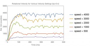
In this case, the velocity setting of 4000 never quite reaches the target. This is due to driving the robot with only one tread, and the other tread is rubbing against the table. For the other values of velocity, there is a little overshoot and they settle relatively quickly. The most exciting part about this is that I can hold the wheel and feel the power increase to attempt to maintain a constant rotational velocity. I can also drive this at low speeds now with the robot stalling.
As another test, I increased the gain to 0.6.
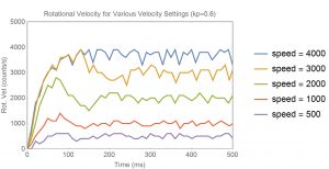
The results are not very different, but the gain difference was minor. At this point, you can see slightly faster rise times, but more overshoot and a dampened oscillation. If I look at the actual power levels calculated in the program, I get this:
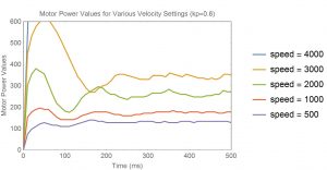
Keep in mind that anything above 400 is automatically limited to 400 in the library function for setting the speed. At a speed of 4000, we are not able to drive the motors enough and the regulation fails. However, at lower rotational velocity levels, you can see how the power is initially driven higher, then reduced in order to maintain a constant speed.
At this point, I could tweak the Kp value to get the best response for a given speed, but I’d rather wait until the next post and add a full PID controller. The PID should work over a broader range of power values with a faster response and cleaner settling.