
The next several posts are going to deal with writing functions for regulated motor blocks. So far, everything shown in this blog for the Zumo uses unregulated motors. At some point, having regulated and synchronized motors will be necessary for precise navigation. Since I have some time on my hands now, I figured I’d begin tackling it.
First of all, what is motor regulation? In this case, I’m referring to a method of maintaining constant rotational velocity, as opposed to a constant power applied to the motors. The actual power applied to the motor will fluctuate to maintain a specific rotational velocity.
Why do we need motor regulation? Well, there are several reasons, and I’m only going to touch on a few. First of all, if you look at the schematic, the H-bridges that drive the two motors operate off of the battery voltage, not the voltage after the motor regulator. Therefore, as the battery voltage changes, the velocity of the robot changes. Another reason is to deal with motional resistance better. Let’s say the robot is driving at a speed of 200, then it hits an object. The robot will naturally slow down and the power will stay at 200. However, if using a regulated motor function, the robot measures the rotational velocity of the wheels, notices that it slows down, and increase the power to maintain a constant rotational velocity (up to the limit). Another great reason to use regulated motor functions is for low velocity, precise movement. If you want the robot to move very slowly, it often will stall under lower power levels. Motor regulation will dynamically adjust the power to allow it to move precisely at low velocities.
This topic will be split over several posts. The content is written primarily for my middle school robotics kids. People who understand control theory will think it’s too easy, people using the Zumo after using the EV3 may think it’s overly complicated. If you have any questions, please send me a note through the “Contact Me” tab and I’d be happy to help you out.
This post will deal first with setting a power level, and measuring the rotational velocity. In all cases, I’m leaving the velocity in terms of encoder counts on my 75:1 Zumo robot. Velocity is simply the change of encoder counts divided by the change in time. I can control the change in time by setting how fast I sample the measurements. For reasons that will become clear later the regulated motor topic, we don’t want to sample too fast. For now, let’s sample at about 10 ms.
The code below turns the motors on at a power of 300 for a short distance, calculates the rotational velocity, and outputs the velocity vs. time to the serial monitor. I used the output format of “{time,velocity}” to be compatible with Mathematica, which I use for plotting the data.
#include <Zumo32U4.h>
Zumo32U4Encoders encoders;
Zumo32U4Motors motors;
Zumo32U4LCD lcd;
Zumo32U4ButtonA buttonA;
#define dT_MOTOR 10 //Sample time for velocity calculation
#define MOTOR_POWER 300 //Motor power
void setup() {
Serial.begin(115200); // initialize Serial communication
while(!Serial);
lcd.clear();
}
void loop() {
int newPosition, oldPosition;
int vel;
unsigned long startTime, lastSampleTime;
lcd.print("Press A");
buttonA.waitForButton();
lcd.clear();
delay(200);
startTime=millis(); //Record the start time
lastSampleTime=millis(); //Initiallize the time of the last sample
oldPosition=encoders.getCountsAndResetLeft();
Serial.print("{{0,");
Serial.print("0},");
motors.setSpeeds(MOTOR_POWER,MOTOR_POWER);
do {
if(millis()-lastSampleTime>dT_MOTOR-1) { //If current time-lastSample >= sample time....
newPosition=encoders.getCountsLeft();
vel=(newPosition-oldPosition)*1000/dT_MOTOR;
oldPosition=newPosition;
lastSampleTime=millis();
Serial.print("{");
Serial.print(millis()-startTime);
Serial.print(",");
Serial.print(vel);
Serial.print("},");
}
} while(encoders.getCountsLeft()<500);
motors.setSpeeds(0,0);
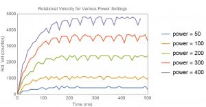
} The chart below shows typical data for various power levels. Note that there is some ripple from due to rounding at the sampling times. If I were to run the same conditions, but had the robot pushing an object, the robot would slow down considerably. Also, notice in the plot how the rise time for the slower speeds appears fairly slow to settle. Regulation should speed that up considerably by applying more power at the start to overcome the robot inertia.
In the next post, we will put the motor in a proportional feedback loop to provide a low order of regulation.