
The IR sensors on the Zumo 32U4 left us wanting with a desire for a lot more range. We came across the VL53L0X Time-of-Flight range finding module. The VL53L0X is capable of up to 2 m range with mm level resolution, and boasts that it is insensitive to ambient lighting conditions, angle of target object, and reflectivity of target object. Seems too good to be true, so we tried it out. This post discusses how to hook up a breakout board (manufactured by Pololu) to the Zumo 32U4 and how to take data.
The time of flight sensor uses a VCSEL diode (a type of laser diode) to transmit a pulse of IR light. The light hits an object, a small portion is reflected back, and the module uses an avalanche photodiode to detect and amplify the pulse. The module then compares the time difference between when the pulse was sent out and when it was received to determine the range. It’s a pretty neat module, especially considering that the speed of light is 3e8 m/s, and 1 mm resolution would mean that it can sense time differences in the 1 ps range.
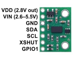
Above is an image from the Pololu website for the module and breakout board (https://www.pololu.com/product/2490). At about $14, it is hard to beat. The module uses a 5V I2C protocol, which makes it very easy to interface with the Zumo 32U4. The image above shows the external connections to the board. However, all we need to really worry about is Vin, Gnd, SDA, and SCL.
Vin is the input voltage to the module. This particular board has a voltage regulator that can take a range of input voltages, and regulated it down to the correct level for the ToF module. Gnd is the ground reference. SDA and SCL are the I2C pins for Serial Data and Serial Clock. To go into the workings of I2C is beyond the scope of this post, but all you really need to understand for now is that we need to hook these connections up to the equivalent pins on the Zumo.
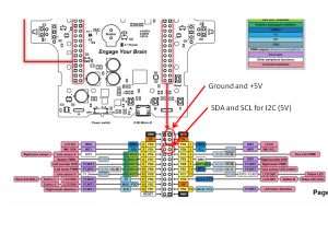
The above image is taken from the Zumo 32U4 pinout document from the Pololu website (https://www.pololu.com/file/0J864/zumo-32u4-pinout.pdf). Note that the right side expansion port has ground, 5V, SDA, and SCL thru-holes that we can attached pins to. How convenient!
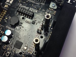
I soldered some 0.1″ pins into these thru-hole pads. There is a nice access window in the chassis where the batteries go to allow access to the solder pads from the underside. I also added some 2-56 stand-offs to allow me to attach a thin plywood platform to mount the sensor to the robot.
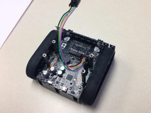
I then built up a 4-wire harness to connect the Zumo connections to the ToF sensor pins. You can use 6″ female-to-female jumper wire as well if you don’t want to build a custom wire harness.
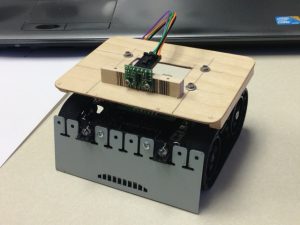
The picture above shows the ToF sensor mounted to the wood platform with the wire harness attached. The sensor breakout board has 2 mounting holes where I used 2-56 socket head screws to mount the sensor to the platform. Note that I could not use a washer as it interferes with some of the components on the board.
The next post will discuss how to write a program to read from the sensor as well as optional methods of configuring the sensor.